- Home
- Schools
- Learning material
- Class Set Gears
Make the basics of different types of gears understandable and sustainable!
How does a bevel gear, a belt drive or a rack and pinion drive work? What happens when the transmission ratio changes? These and many other questions are explored by the young researchers using 15 models and twelve experiments. The models are quick and easy to set up in the classroom and can be put to optimum use with the ready-made tasks and solutions.

Gears play a central role in the history of mankind. Simple gears were used to make fire, more complex ones were needed to build structures such as Stonehenge (ca. 3,500 BC) or the seven wonders of the ancient world, including the pyramids of Giza (ca. 2,500 BC), which can still be admired today.
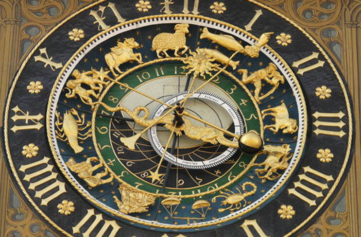
Gears were crucial for the development of human civilization: they made it possible to construct large buildings, draw water or lift and transport heavy objects. Later, they were used to generate energy (pedal wheels, water wheels, windmills, steam engines), pump water (Marly machine) or drive vehicles. Gears also played an important role in measuring time: it was only with pendulum clocks and precision mechanical gears that it was possible to construct clocks with which time could be determined more precisely than by determining the position of the sun.
Today, gears are found in almost every electrical appliance, usually invisible to the user. Washing machines, dishwashers, vacuum cleaners, sewing machines, bicycles, elevators, hair dryers, blenders, coffee machines, garage doors, wall clocks, scales - none of these technical achievements of everyday life would be possible without gears. Even the simplest tools such as corkscrews or bottle openers are gears. Without gears, we would probably still be living in caves. And possibly not have survived the dinosaurs.
Definition
What exactly is a gearbox? A gearbox is a technical component (also known as a “machine element”) that is used to change movement variables. What does this mean?
The movement of an object (or “object”) can be described by the direction, the path (or “position”), the speed and the type (rotational movement, back and forth movement). A gear changes one or more of these properties, which we also call motion variables. Every gearbox has an “input”, the so-called drive, where, for example, a crank, a motor or another machine element transmits force, and (at least) one “output”, the output drive, where a movement or force is transmitted to another machine element.
Let's illustrate this using what is probably the simplest transmission of all, the lever.
A lever consists of a rigid body (e.g. a beam) that is pivoted at one point. Imagine a seesaw on a playground - that's exactly what a lever is. The two parts of the seesaw beam that protrude to the left and right of the bearing are called the lever arm. One of the lever arms is the drive, the other is the output. If you sit on one side of the rocker, your lever arm moves downwards and the other upwards - a rocker (a lever) therefore changes the direction of movement. It also changes the path of the movement, because your movement of one lever arm is transferred to the end of the other lever arm. And the lever can also change the speed of the movement: If your lever arm is longer than the lever arm of the output, then you will cover a longer distance than the end of the other lever arm when rocking - but in the same amount of time. So the movement of the output slows down.
Something fascinating happens: The force that you exert on the drive lever arm of the seesaw with your weight is transferred to the output lever arm. If this is shorter than the drive lever arm, the force increases! You have probably observed this before: If a larger child is sitting on one side of the seesaw than on the other, the seesaw can be balanced by the larger child shortening its lever arm by sliding forwards (towards the pivot joint). So a gearbox can do something else: it can amplify force.
Simple gears such as the lever or pulley have been known to man for thousands of years and were mainly used to lift loads (e.g. in buildings or for loading and unloading ships and carts).
The oldest known records in which gears were systematically studied date back to the Greeks. As far as we know, the “law of the lever” was first described by Archimedes of Syracuse (approx. 287-212 BC). He was so enthusiastic about increasing the force of a lever that he even exclaimed: “Give me a fixed point in space and I will unhinge the world.”
The Roman architect and master builder Marcus Vitruvius Pollio (Vitruvius, ca. 75-15 BC) wrote the first ever work on architecture with his “Ten Books on Architecture” (still extant today). He dedicated volume 10 to “Mechanical Engineering” and described in detail the machines and gears known at the time. These included the pulley block, the corrugated wheel, the treadwheel, the trispastos (a simple crane), Greek water clocks and the Archimedean screw (a “screw” for pumping water). The works of the Greek Heron of Alexandria (probably a contemporary of Vitruvius) also contain “automata” with gears, e.g. a wind-driven organ or the first cogwheels. The Romans also constructed war machines (throwing machines and slingshots) in which gears were used.
A few centuries later, gears played an important role in energy generation. Water power and wind power were converted into rotary motion by water and wind wheels. This was sufficient for mills; for stone saws, however, the rotary motion had to be converted into a reciprocating motion of the saw. The first evidence for the existence of such slider-crank gears is provided by the “drawing” of a stone saw with a water wheel on a tombstone from the 3rd century AD.
Gears experienced a heyday during the Renaissance, when the “ancient writings” of the Greeks and Romans were rediscovered. The drawings of Leonardo da Vinci (1452-1519) in particular contain numerous gears for construction machinery, war machines and the first vehicles.
We have the Dutchman Christiaan Huygens (1629-1695) to thank for the first pendulum clock, which was created in 1657. The precision gearing achieved a rate accuracy of a few seconds per day, which was unbelievable for the time. After the invention of the balance wheel, pocket watches became fashionable. In 1759, John Harrison (1693-1776) solved the “longitude problem” - the precise determination of longitude on the high seas - with such a precision pocket watch, which was only four seconds wrong on a sea voyage lasting several months.
With the development of motorized “automobiles”, gearboxes became even more important in the 19th and 20th centuries. They had to transfer the engine's drive power to the wheels with the highest possible efficiency. To do this, they needed manual and differential gearboxes.
The first systematization of gear elements comes from the Swede Christopher Polhem (1661-1751), who founded the first engineering school in 1697 and developed a “mechanical alphabet” with models of elementary gears. Almost a hundred years later, Franz Reuleaux (1829-1905) developed a gear system that became established as the standard in mechanical engineering.
We can categorize gears in different ways, e.g. according to the change in motion they cause, according to the components they contain (rollers, gears, cranks) or according to the type of power transmission. Many gearboxes result in several changes of motion and can be realized with different components, so the classification into categories is rarely clear.
In the following, we differentiate gearboxes somewhat simplistically according to the change in motion that they cause:
We get to know several types of gears, the properties and function of which are explored in greater depth in various tasks.
For secondary level I+II students, some special and more complex gears are then presented.
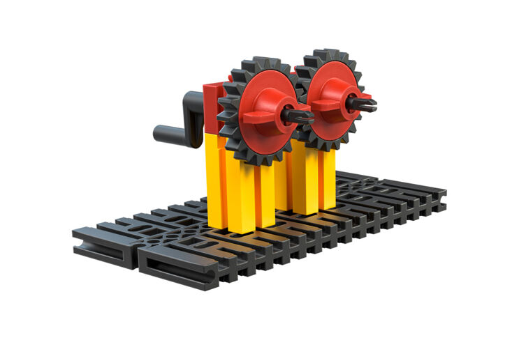
Gear drives
In gear drives, motion is transmitted via gears. It is said that the gears “mesh” when the teeth of two gears mesh. The fischertechnik gears are designated by the number of teeth they have: For example, a Z20 is a gearwheel with 20 teeth.
Gearwheels allow a simple calculation of the transmission ratio, i.e. the change in the speed of movement: The ratio of the rotational speeds of two axes of a gear corresponds to the reciprocal of the ratio of the teeth of the meshing gears on these axes. Example: If there is a Z10 on the drive axle and a Z30 on the output axle, then the drive axle rotates three times as fast (30:10 = 3:1) as the output axle - you have to turn the crank on the drive axle three times for the output axle to rotate once around itself.
In gear drives, the edges of the teeth rub against each other. This friction results in a power loss of around 10%. The friction can be reduced by increasing the “play” (the distance) between the teeth. However, this makes the transmission imprecise: you can move one of the axles a little without the other axle moving.
Specially shaped gears are used in an attempt to reduce this disadvantage in practice. Gear drives are mainly used in motor transmissions.
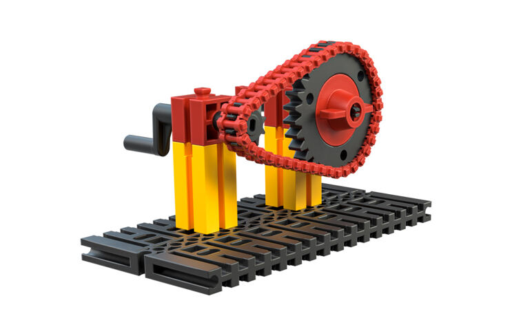
Chain transmission
Instead of allowing the teeth of the gears to mesh directly with each other, they can be connected by a chain - you know this transmission from bicycles. In this case, the direction of movement is not changed; the drive and output axles (in the case of a bicycle, the pedal axle and the rear axle) rotate in the same direction.
The transmission ratio can be determined from the ratio of the teeth of the gearwheels to each other, as with the gear transmission. Because the teeth mesh with the chain links, the loss of power due to friction is significantly lower than with a gear transmission.
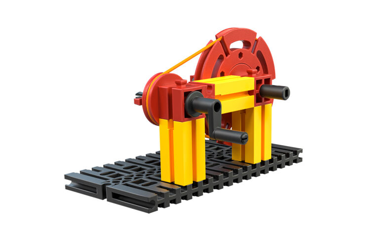
Belt drive
In a belt drive, the power is transmitted from the drive to the output via a belt. With fischertechnik, this is a special rubber belt; alternatively, a house holding rubber can also be used. A belt drive has built-in “overload protection”: If the output is not strong enough to drive a machine element connected to it, the belt slips as soon as the force acting against the static friction is greater.
In contrast to the chain drive, the direction of the output movement can be changed by crossing the belt (in the form of an “8”). If the belt is flexible, the distance between the drive and output axes can even be reduced or increased during “operation” of the gearbox.
The power loss of belt drives is significantly lower than that of a gear drive, as there is no significant friction. It is even smaller than that of a chain. This is why belts were also used in cars in the past, and there are also bicycles and motorcycles with belt drives. However, belts wear out more quickly than a (well-maintained) chain and therefore need to be replaced more frequently.
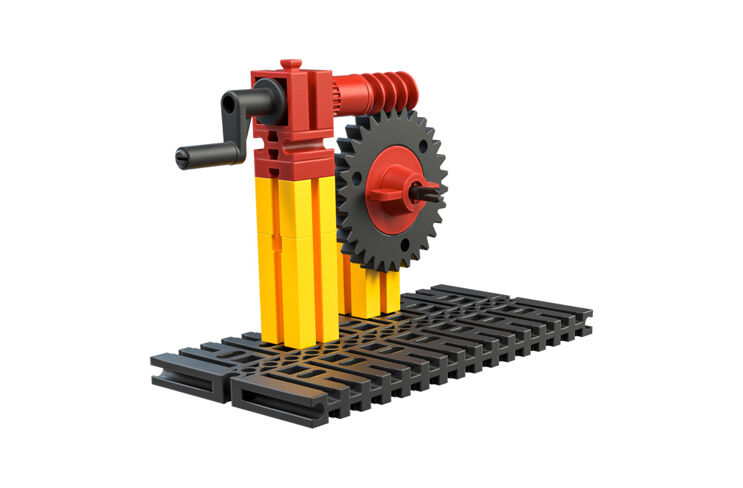
Worm gears
Worm gears transmit the rotary motion of an axle to the teeth of a gear wheel via a worm thread. Each revolution of the worm thread turns the gear wheel one tooth further. As the output axis must run perpendicular to the drive axis, a worm gear also ensures a change in the position of movement.
Calculating the transmission ratio for a worm gear is very simple: The rotational speed of the drive axis (the worm) is n times as high as that of the output axis if n is the number of teeth of the gear wheel on the output axis. So: If the worm drives a Z30, then the output axis must be rotated 30 times for the output axis to rotate once. Worm gears therefore translate “very strongly” into slow speed and enable compact gears with large ratios.
A worm gear is “self-locking” and therefore only works in one direction: from the worm to the gear wheel. A worm gear therefore always provides a transmission ratio in the slow direction.
The disadvantage of a worm gearbox is the large power loss of up to 30%, as the worm continuously rubs against the teeth of the gearwheel.
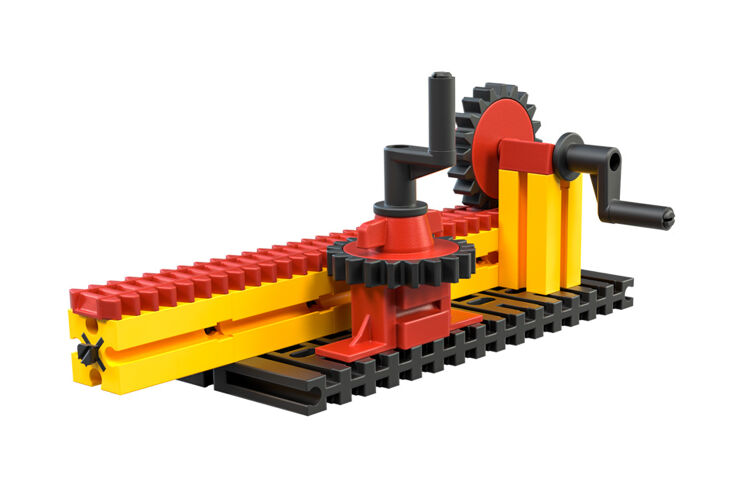
Toothed rack
When a rotary movement is transmitted via a gearwheel to a gear rack, the position of the movement (the axis with the gearwheel is perpendicular to the direction of movement of the gear rack) and the type of movement (a rotary movement becomes a thrust movement) change.
Friction losses also occur with a gear rack, which are usually higher than those of a gearwheel transmission (i.e. more than 10%). Unlike the other gearboxes we have seen, the effect of the gearbox is limited by the length of the rack: Once the end is reached, the rotary motion of the drive can no longer be implemented. Rack and pinion gears are therefore used, for example, in sliding doors or forklift trucks, but rack railroads also use the principle.
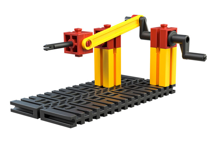
Sliding crank
A slider-crank gearbox also converts a rotary movement into a horizontal movement. However, it does so continuously, in a back and forth movement. It is therefore not limited.
However, unlike the gearboxes we have already seen, the transmission is not uniform: as the crank rotates, the speed at the output changes. Although the gearbox is not self-locking like the worm gearbox, if the back and forth movement is selected as the drive, the gearbox has a “dead center” at the end of the back and forth movement: If it stops exactly there, the movement jams and can no longer be continued.
Sliding crank gears with the back and forth movement as the drive played a central role in steam engines and are still used in engines today: they convert the up and down movement of the piston into a rotary movement. To overcome the dead center, several drive pistons are used, which operate slightly offset to each other.