The E-Tronic building set deals with exciting topics in electrical engineering / electronics. To start, we will look at the basic features of simple electrical circuits. Then, we will be learning about a variety of electronic components such as resistors, capacitors and transistors. We will be showing you how to install and control these exciting components in different circuits and devices based on several models and practical examples.
History
The history of the field of electronics / electrical technology reaches back to the 17th and 18th centuries. 19th century scientists built on this legacy. Alessandro Volta, for instance, developed the Voltaic pile, which was the first functional battery. Philipp Reis invented the telephone, and the capability for electrical voice transmission. The lights went on around the world in 1879 thanks to an innovation by Thomas Alva Edison - the carbon filament light bulb.
Erasmus Kittler established the world’s first degree program in electrical engineering in 1883 at the Technical University of Darmstadt. In 1884, Heinrich Hertz succeeded in proving the existence of electromagnetic waves. This was the beginning of wireless radio transmission.
J Ambrose Fleming invented the first radio tubes around 1905. Manfred von Ardenne used a cathode ray tube to create the first electronic television.
Another milestone in electronics came in 1941, when Konrad Zuse built the world’s first functional computer.
The invention of the transistor triggered the age of the tube. This allowed many new devices to be built to be very compact. In 1958, Jack Kilby developed the first integrated circuit (IC). This development was what made today's processor chip technology, and the development of modern computers, possible.
You probably already understand how important these inventions were, and how they still enrich our everyday lives today.
Basic principles of electronics
Where does the term “electronics” come from? Electronics comes from the Greek word “Elektron”. You might say it's actually composed of two words, the terms “electron” and “technology”. Electronics, therefore, is electron technology.
The field of electronics can be divided into five areas:
You will be learning about three of these areas in more detail: Analogue and digital electronics, and the logic of digital electronics.
Power supply
Normally, you will be using the 9V block battery in the battery holder for all of the experiments in this building set.
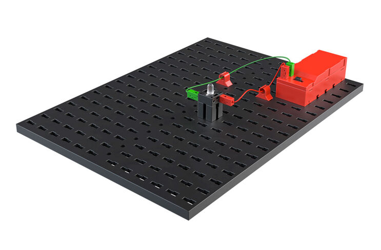
Connect an LED to the power supply. to do so, build the “simple circuit” model based on building instructions.
We use symbols to represent a variety of components in electrical engineering.
Task: What do you observe when the LED is connected to the power source?
Answer: The lamp is illuminated. If you remove a cable, the lamp will go off again. You have built a circuit, and the current truly does flow through it in a “circle”. It flows from the positive terminal of the power supply, through the red sire to the lamp, then through the green wire back to the minus terminal of the power supply. If you interrupt the circuit at a certain point, for instance by disconnecting a plug, then the current cannot flow.
Simple circuit with push button
You will be using a new component in your model of a simple circuit with button – the push button. You will need it to connect the circuit to the LED or interrupt the circuit.
Use the building instructions to build the model, then wire the electronic components according to the wiring diagram. As you can see from the wiring diagram, the push button has different switching positions.
Technical information for the push button:
The push button has three connections. Depending on the application, you can use the button ...
as a normally open contact: Contacts 1 and 3 are connected.
… as a normally closed contact: Contacts 1 and 2 are connected.
Task:
Decide whether the push button should function as a normally open or normally closed contact.
Continuity tester
A continuity tester is an important measurement instrument used by electricians. It can be used to determine whether there are any interruptions in an electrical circuit or a cable. Build the continuity tester and wire the electronic components as shown on the wiring diagram.
Do you already have an idea of how it could work? Then go ahead and try it out. As you can see on the wiring diagram, you will need two open contacts, both on the cable to be tested. If the cable is OK, current will flow and the LED will output a visual signal. If the cable is defective, or interrupted, the LED will stay off.
Task: Test a variety of materials using the model. Which materials conduct electrical current, and which do not? You can use wood, metal, or paper for instance.
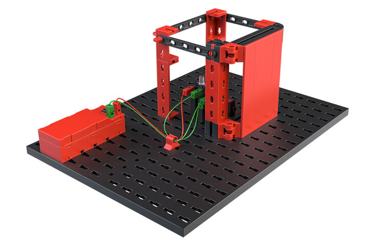
Refrigerator light
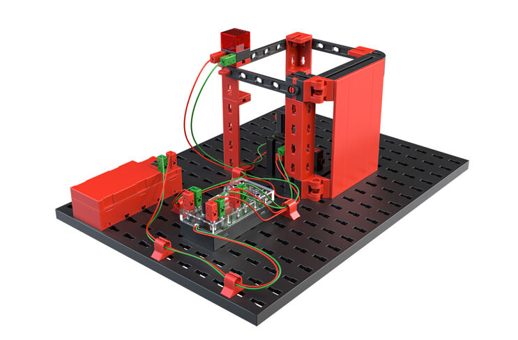
The button functions will be implemented in the refrigerator light model. Build the model and wire the electrical components. How does the refrigerator light work? When the door is opened, the interior light should go on. When you close the door, the light should go off again.
Task: For this task, decide whether the push button should function as a normally open or normally closed contact.
You will be learning about series and parallel circuits in the next two tasks. To do so, you will build a variety of models using the building instructions.
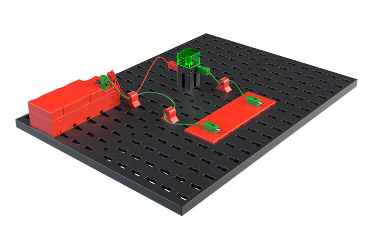
Series circuit with machine
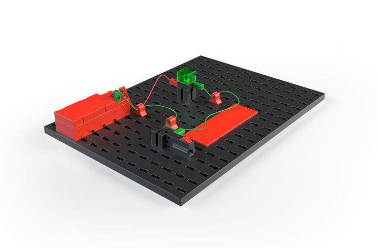
Machines are used to manufacture components in an industrial setting. The operator has to press a button with each of his hands to start the working process - this ensures his hands do not become caught in the machine. These buttons are wired in series. This is also called an “And circuit”.
When buttons 1 AND 2 are pressed, the machine's motor starts up. You can also represent the switching states using a table.
Build the machine to demonstrate a series circuit. You will be using a new component to do so, the motor.
Task: Research online to learn about how a direct current motor works. What happens if you exchange the connections of the motor?
Parallel switching
You want to be able to open the front door of your house from your room, and using the intercom system. You can do so by switching two buttons in parallel.
The button arrangement is known as an “Or circuit”. If button 1 OR button 2 are pressed, or if both buttons are pressed, the door opener is activated. You can also represent the switching states using a table.
Build the electric door opener demo model to simulate a parallel circuit. You will use the LED from the building set as a replacement for a door opener. You can see the switching symbol for the door opener on the wiring diagram.
Multiway switching - corridor lighting
Multiway switching is used to turn one or more lights on or off from two different points. It is used in small corridors, entryways and rooms with two entrances. You will need two buttons from the building set for the circuit. Build the model based on the building instructions, and wire the circuit.
Task: What happens if you press one of the buttons (switches) in your model? What happens if you press the second button (switch)?
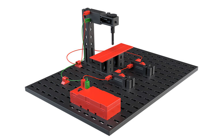
Elevator with polarity reversing switch
Certainly, you have already noticed that there is a switch with three positions on the battery holder. This switch is called a crossover switch or polarity reversing switch. It is a switch with four connections. Two of these are connected to each other. When the switch is activated, the connections are reversed.
Task: Try to build the circuit for the polarity reversing switch using your two buttons, then insert it directly into your model.
Resistors
A resistor is a passive component with two poles, and is measured in ohms (Ω). Resistors are used to:

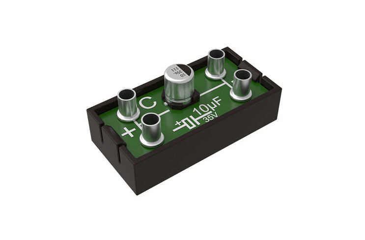
Capacitor
A capacitor is an electrical component that is capable of storing electrical charge and the associated energy. It consists of two metal plates of the same size (electrodes).
These are separated from one another by an insulating material “dielectric”. But how does it all work? A flow of current through one capacitor negatively charges one of the electrodes, and positively charges the other. This means that the charge V formed on the metal plates is stored.
You will use the capacitor as an element to determine frequency in the following models. Along with a resistor, you can determine the length of time that an LED should flash. The capacity of the capacitor is indicated in farads (F).
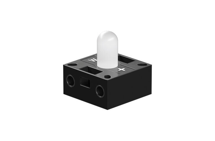
LED
An LED is a semiconductor component that emits light. This abbreviation stands for light emitting diode. When electrical current flows through the diode, it emits light. The wavelength (colour of the light) depends on the semiconductor material and doping.
The cathode (−) is marked by a flat area on the base of the housing.
Important: The LEDs used in the building set are installed in a lamp. You just need to ensure the correct polarity, as indicated in the building instructions.
Generally, LEDs work with a voltage of 2 V and a current intake of approx. 20 mA. Your battery provides 9V voltage. Therefore, you must add an upstream resistor to consume the other 7 V. The size of the resistor can be calculated using Ohm's law.
R (resistance) = U (voltage)/I (current) or 7 V/0.02 A = 350 Ω
Important: The LEDs you are using in your building set do not require an additional series resistor. This is already installed in the LED housing.
Transistor
The transistor, also called a bipolar transistor, is another electronic component. It is used to switch and amplify electrical signals. Transistors are the most important components in electronic circuits. Transistors are particularly key in integrated circuits. The name transistor is derived from the component's function. If the resistance in a semiconductor layer changes, the resistance in the other layer is also influenced. “Transfer resistor” became the term transistor.
Task: Learn about the function and use of a transistor as a switch. There is plenty of information available online about this topic.
Simple blinker
Wind turbines, broadcasting masts, radio towers, and aeroplanes have flashing lights for safety reasons, to provide a visual indicator of their position. Build the flashing circuit demo model and wire the electronic components as shown on the wiring diagram.
The capacitor is initially an empty charge storage device. While it is being charged, base current cannot flow to T2, and LED 1 will go out. Base current only flows again, and the LED only turns back on, and the capacitor is sufficiently charged.
Touch sensor
Touch sensors are used very frequently as switches for opening doors or turning on lights. The switch design is called the “Darlington switch” in the technical jargon. Build the circuit according to the building instructions.
Task: Touch the two blank ends of the plug contacts with two fingers. What happens? What happens if you touch the plug with completely dry fingers?
The LED is illuminated because of the current amplification provided by the two transistors. This amplification is sufficient to create an effective touch-sensitive switch. Why resistor R1? It protects the two transistors against too much current when you connect the two contacts directly.
Task: Touch only the contact that leads to the base of the Darlington circuit and move your feet on the ground. What happens to the LED?
This will generate more or less charge depending on the ground properties and material of the soles of your shoes (static charging). This causes the LEDs to flicker.
Task: Replace the LED with a motor. Is it possible for the Darlington circuit to activate a motor so that it runs?
Power supply
The E-Tronics module only works if you connect it to a 9 V power supply. To do so, use the battery holder with a 9 V battery. Ensure the correct polarity when connecting the battery (red = plus). If the module is supplied correctly with current, the green LED will be illuminated.
Inputs I1 - I3
You can connect fischertechnik sensors to these inputs. They deliver information to the module. Buttons, a reed contact, and electronic circuits are available to serve as sensors.
Motor M1 and M2 outputs
You can connect a motor, an LED or an electronic circuit to the outputs. How the outputs are switched depends on the selected program and the status of the inputs.
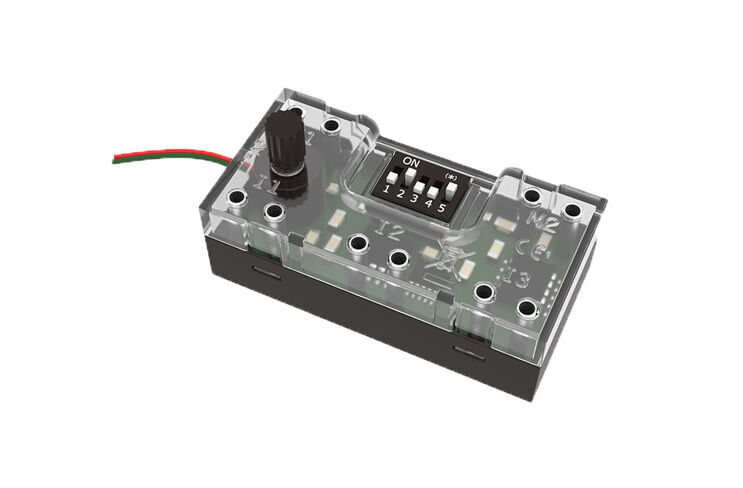
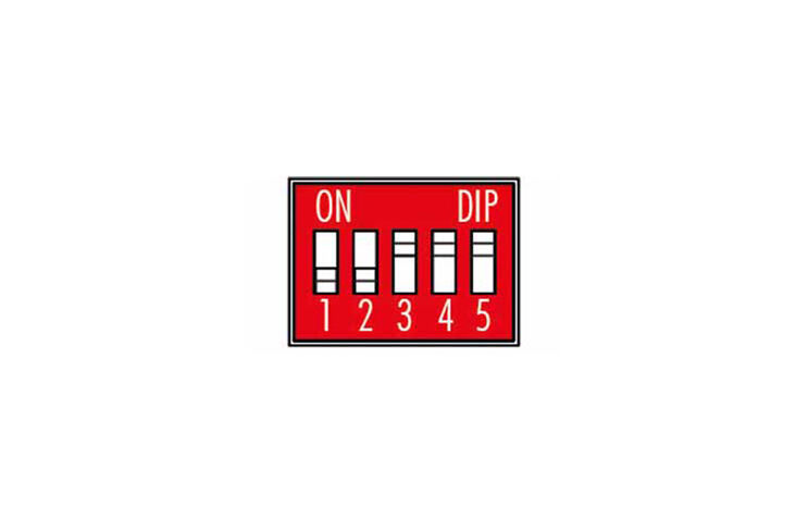
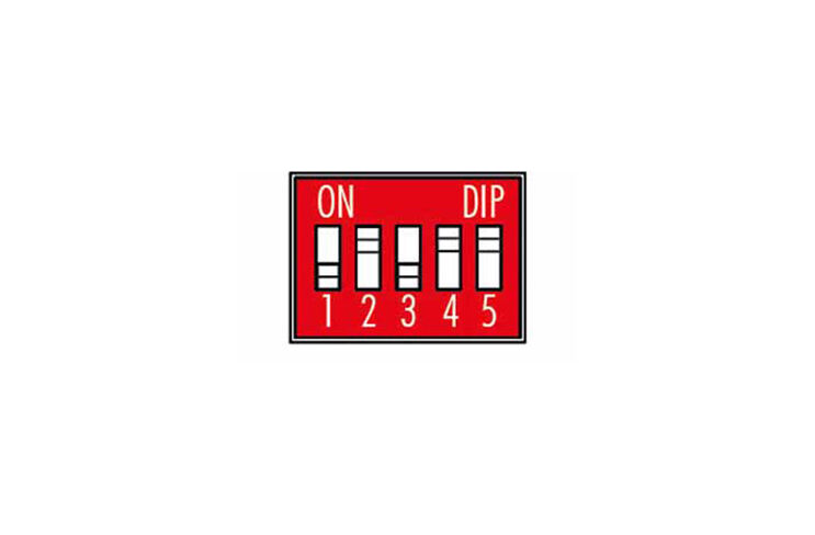
Slide switches (DIP switches) 1-5
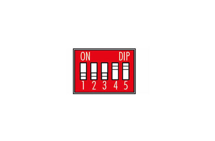
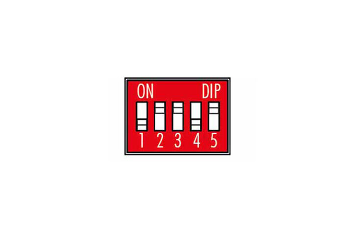
The positions of the five slide switches, also called DIP switches, determine the function of the E-Tronics module. You use these switches to set the desired program. Ensure that the DIP switches are in the position required for the specific model. Each switch has two positions: “ON” (up) and “OFF” (down).
Set all DIP switches to “OFF” before you start your experiments.
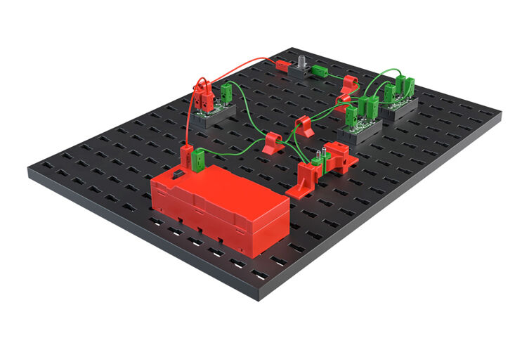
Functional model with E-Tronics module
Important: The E-Tronics module checks which program it should execute when the power supply is switched on. Therefore, always set the desired program first, then connect the power supply.
If DIP switch DIP5 is set to “OFF”, then the so-called basic program is activated. This is a universal program you can use to control a variety of models. Use the functional model with E-Tronics module for the exercises on the basic program. Connect the electrical components to the E-Tronics module as indicated in the building instructions.
A new sensor is used in this model, called the reed contact. This is a switch that is closed once a magnet comes close to it. You will connect the reed contact to your functional model at input I3. There is also a magnet to close the switch in the building set:
Task: Briefly press the button on I1 - the motor turns. Press the button on I2 - the motor turns in the other direction. Stop the magnets on the reed contact on I3 - what do you observe?
Slider switches 1-4 have special functions in the basic program:
DIP1 - DIP3: Reverses the function of the inputs. If DIP switch 1 is set to “ON”, then the input is activated when the button is released. This function is useful, for instance, when using a light barrier. The input is activated when the light barrier is interrupted.
Task: Consider how you would need to set DIP3 so that the motor would stop once you remove the magnets from the magnetic switch.
Task: Use the potentiometer to change the rotational speed of the motor.
DIP4 (0) can be used to control the motor speed on M1 using the potentiometer, or poti for short, in the base program. This changeable resistor was installed in the electronics module. If the switch is set to “ON”, the flashing frequency on M2 can be changed.
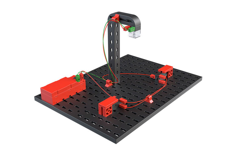
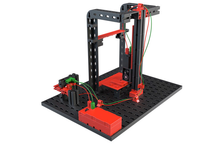
Ball run
The ball run is the first “real” model you will control with the base program of the E-Tronics module. To do so, build the model from the building instructions and set the DIP switch on the E-Tronics module as follows:
You can use the button to start the motor. Once the magnet transporting the ball upwards arrives at the reed contact, the motor stops. Once the ball comes down the track, it activates the button below the track and the motor starts up again to transport the ball upwards.
Task: The motor can be started by either one of the buttons. What is this kind of switching called?
Answer: Parallel switching
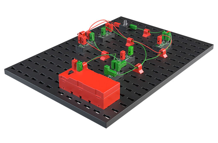
Alarm system
The alarm system is the first model for which there is a specialised program. Build the alarm system according to the building instructions, and connect the electrical components to the E-Tronics module.
Set DIP4 to “ON”. You have now accessed the program to control the alarm system. How should the program function? Once the door is opened, the red lamp (LED) begins to flash. If the door is closed, the LED continues to flash. Only when another button (that switches off the alarm system) is pushed does the LED go off. You can use the specialised program to build a real alarm system. You can even use it to secure the door to your room against unauthorised access.
Elevator controller
The elevator you previously equipped with a reverse polarity switch can also be controlled using the E-Tronics module. A specialised program is used in this case as well. Set the DIP switch on the E-Tronics module as follows:
Once you activate the reed contact using your magnet, the elevator will move to the other floor, meaning it will move up if it is at the bottom, or down if it is at the top.
Task: What are the advantages of this type of controller for the elevator, in contrast to controlling it with the reverse polarity switch you have already tried out?
Answer:
Bathroom ventilation
If you cannot ventilate a bathroom by opening a window, then machine ventilation is necessary. You may have seen this in a public bathroom, when you hear a fan turn on automatically.
In your fischertechnik bathroom ventilation, the fan goes on when the light is switched on. When you switch the light back off, the fan will continue running for several seconds, then it will go off as well. You can use the potentiometer to set how many seconds it should continue running. (0.5 sec - 5 sec)
Set DIP3 and DIP4 to “ON”. You have now accessed the program to control the bathroom ventilation.
Garage door
A garage door activated by a motor to open and close automatically is very convenient. You may have this kind of garage door at home.
Build the model based on the building instructions, and wire the electrical components. Set the DIP switch as shown on the wiring diagram.
How should the garage door work?
You will start the program, and the door will close. The light will also switch to red. If you hold the magnet against the reed contact, the garage door will open. If the door is open, the light will switch to green. The touch switch ensures the door closes. First, the light will switch to red.
Task: In technical terminology, what is the electronic circuit for the touch switch called?
Answer: A Darlington circuit
Specialised program for digital technology
After you have completed all of the models in the building set, we want to show you what other functions the E-Tronics module offers. You can certainly use these functions for your own model ideas. There are programs provided that you can use to build logical circuits (monoflop, flip-flop, AND and OR functions). Of course, this is even more fun when you link multiple E-Tronics modules together.
Since this goes beyond the scope of this building set, you can find more information on these functions in a separate area.
Fehlersuche
Es ist immer frustrierend, wenn du ein Modell aufgebaut hast und es nicht so funktioniert, wie du es gerne hättest. Deshalb hier ein paar Tipps, wie eventuell auftretende Fehler behoben werden können.
Wichtig: Das eingestellte Programm wird nur beim Einschalten des E-Tronics-Modul abgefragt. Stellst du das Programm zwischendurch um, musst du kurz die Stromversorgung unterbrechen, damit das neue Programm aktiviert wird.
Troubleshooting
It is always frustrating to build a model, then find it doesn’t function like you had hoped. Here are a few tips for handling any errors that may come up.
Note:
|
Program |
DIP1 |
DIP2 |
DIP3 |
DIP4 |
DIP5 |
|
Base program:M1: Motor with function: |
|
|
|
|
0 |
|
I1 = Left motor I2 = Right motor I3 = Motor stop |
|
|
|
|
|
|
M1: Motor speed adjustable via potentiometer |
|
|
|
0 |
|
|
M2: Flashing light or motor clockwise/anti-clockwise, frequency 0.5 s |
|
|
|
|
|
|
M1: Motor speed constant |
|
|
|
1 |
|
|
M2: Frequency 0.5 s to 5 s adjustable using the potentiometer |
|
|
|
|
|
|
I1, I2 and I3 as input (NO contact) |
0 |
0 |
0 |
|
|
|
I1, I2 and I3 as input (NC contact) |
1 |
1 |
1 |
||
|
Alarm system |
0 |
0 |
0 |
1 |
1 |
|
Elevator with E-Tronics module |
0 |
1 |
1 |
0 |
1 |
|
Bathroom ventilation |
0 |
0 |
1 |
1 |
1 |
|
Garage door |
0 |
1 |
0 |
1 |
1 |
Key: 0 = “OFF”, 1 = “ON”
Control LED
|
LED |
Description |
|
The LED is illuminated continuously |
Power supply OK, electronics module is ready for operation |
|
LED flashes 1 time |
Input on I1, I2 or I3 |
|
LED flashes briefly 4 times, pause, flashes briefly 4 times |
Short circuit on M1 and/or M2 |
|
LED is not illuminated after switching on the power supply |
Power supply not OK, power supply polarity reversed or electronics module defective (contact fischertechnik service) |
Measuring voltage and current using a multimeter (not included in the building set)
If you have a multimeter, which is a measurement device that can be used to measure voltage, current and resistance, you can definitely use it to complete interesting measurements of the models and components in this building set.
For instance, you can measure to check whether the resistors in the building set actually have the values printed on the circuit board. In addition, you can determine whether your mounted cables are all correctly connected and carrying power accordingly.
You can use the voltage measurement to check whether the battery is still delivering sufficient voltage to supply the model.
You can use the current measurement to check how much current a motor or LED is using.
Try it out for yourself. The operating instructions for the multimeter will show you how to complete a measurement correctly.
We hope you have enjoyed controlling the models in the PROFI E-Tronic building set. Maybe you can build a few of your own models and control them using the E-Tronics module. At some point, the base program will no longer be sufficient to correctly control the models, and there will not be a specialised program to meet your needs.
Maybe your model has multiple motors and multiple buttons, and you want to carry out a specific technical process. If so, you are ready for the next level of control technology. The fischertechnik ROBOTICS program. It includes control modules you can program yourself. The BT Smart Controller is controlled via a smartphone or tablet using the ROBOPro Smart software, and has 2 motor outputs and 4 inputs. You can use the TXT 4.0 controller to control four motors and 3 servo motors at the same time. It also has eight inputs for buttons, phototransistors or reed contacts. In addition, Bluetooth, WiFi, and many other features are available to you.