What is mechanics?
The field of mechanics focuses on forces and how objects move. It describes how bodies react under the influence of forces, and how they change their movement in response to them. Mechanics is divided into different areas, such as statics, dynamics, kinetics or thermodynamics. We will now examine the area of dynamics in more detail. Whenever machines or gears are set in motion, they are dynamic. Dynamics describes a change in linear momentum, such as when a shaft turns, when something moves back and forth or when a gear transmits a force. Dynamics, therefore, is the study of changes in movement. In the following section, you will learn more about what exactly this means.
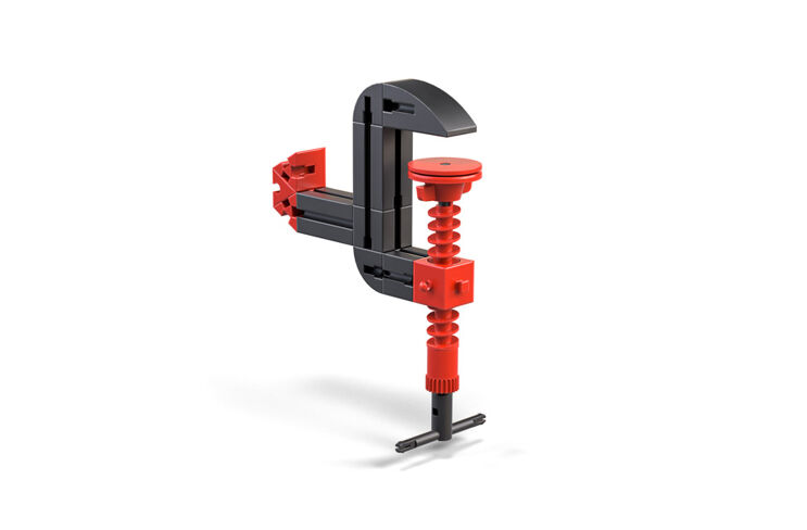
The simplest version of a spindle gear is a spindle turned in a nut. The spindle has a male thread, similar to that on a screw, while the spindle nut has a female thread, just like a common nut. As the nut turns, it moves along the spindle axis. Conversely, the nut can be held tight to cause the spindle to screw into or out of the nut.
Spindle gears are used in many different applications in which a rotational movement needs to be converted into a linear movement.
Spindle gears have multiple advantages:
Challenge
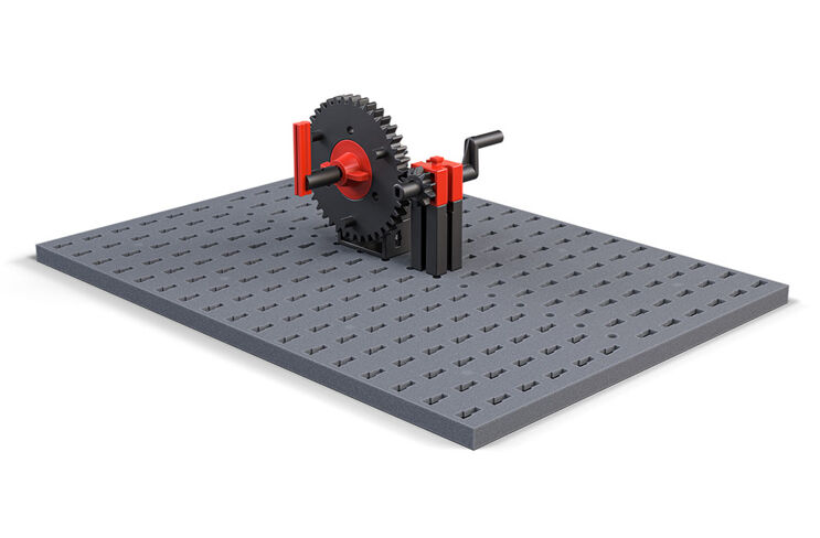
In this section, you will learn more about the gears in gearboxes. Gears are one of the oldest and most robust machine elements. There are many different kinds and sizes of gears. You are probably familiar with the function of gears from bicycles. However, in this case the gearbox is replaced by a chain wheel and chain.
Gear drives can be used to transmit and change rotational movements.
A gear drive can:
In the following models, you will build gearboxes with straight interlocking spur gears. Spur gears are always used when rotational movement needs to be transferred to a parallel shaft.
Challenge:
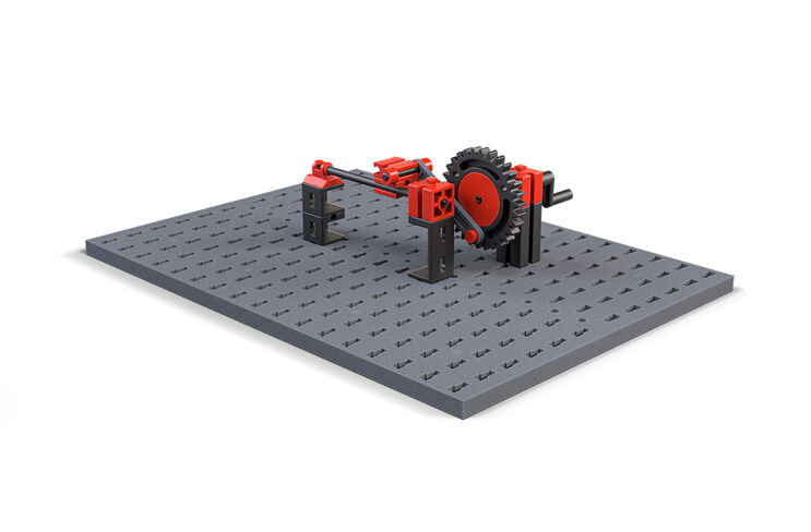
This setup makes the rotational speed 4 x slower, however the torque is 4 x greater in this case. Since the output torque is greater, this kind of gear is called a high speed gear.
However, if you set up the large gearwheel so that the speed is higher but the output torque is lower, then this kind of gear is called a low speed gear.
Challenge:
If you compare the results for the two spur gears, you can understand the interaction between the number of teeth and the number of revolutions. The revolutions needed are always the number of teeth on the output gear divided by the number of teeth on the drive gear. This result is called the gear ratio. In the case of a 3:1 spur gear, the gear ratio is 3, since you need to turn the pinion 3x for the output gear to turn 1x. The output gear has 3x as many teeth as the pinion.
Challenge:
Expert challenge:
Now we have learned a lot about spur gears:
Now it's time to think outside the box - or rather, outside of a straight line: Let’s look at bevel gears.
Challenge:
The gear unit only changes the direction of the rotation of movement by 90°. Because the two bevel gears have the same number of teeth, the torque and speed remain the same.
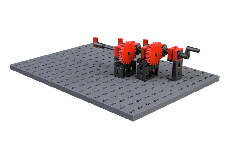
Spur gears can be combined in multiple stages. This can make it possible to achieve even higher/lower ratios:
Challenge:
If you combine different gear stages, the gear ratios are multiplied. For this two-stage spur gear, then, we will take the first gear ratio of 2 and the second gear ratio of 2. This results in a gear ratio between the drive gear and output gear of 2*2=4. We can observe this in action: You have to turn the drive gear 4x for the output gear to turn 1x.
Expert challenge:
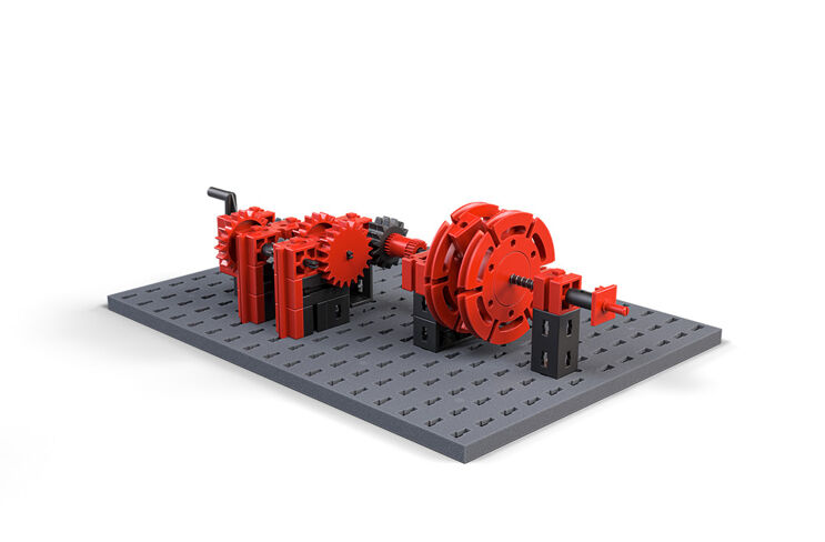
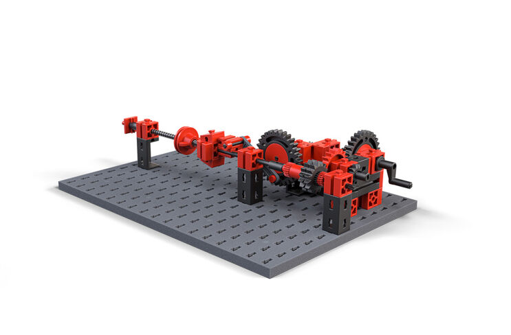
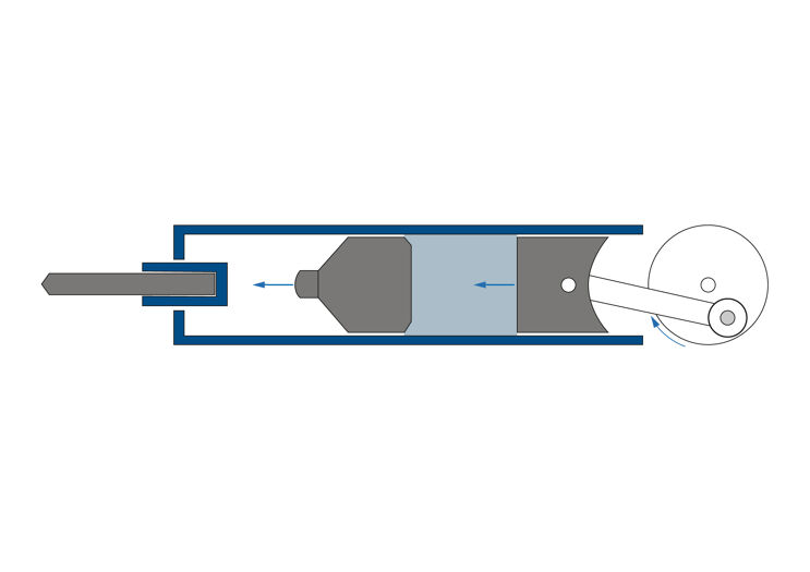
A crankshaft is a device used to convert a rotational movement into a movement back and forth in a straight line.
Challenge:
The transmission for a crankshaft is not even, unlike the other gears we have already learned about: while the crank rotates, the speed of the output changes. The gear is not self-locking like the worm gear, but if the input is a back and forth movement, the gear does have a “dead point” at each end of the back and forth motion. If it stops exactly there, the movement is arrested and cannot be continued.
The crankshaft converts a rotation into a back-and-forth movement. Crankshafts are used, for instance, in sewing machines and hammer drills.
Have you ever drilled a hole in a wall with your parents? A regular cordless drill can be used to drill holes in soft materials like wood or plastic. These cordless drills are generally very simple: a motor drives a multi-stage, high speed gear. You are familiar with this function from the two-stage spur gear you have already built.
If you want to drill a hole for a dowel in a concrete wall, however, a cordless drill probably will not do the job. Because of this, specialised gears are used for these hard materials that chisel while they drill.
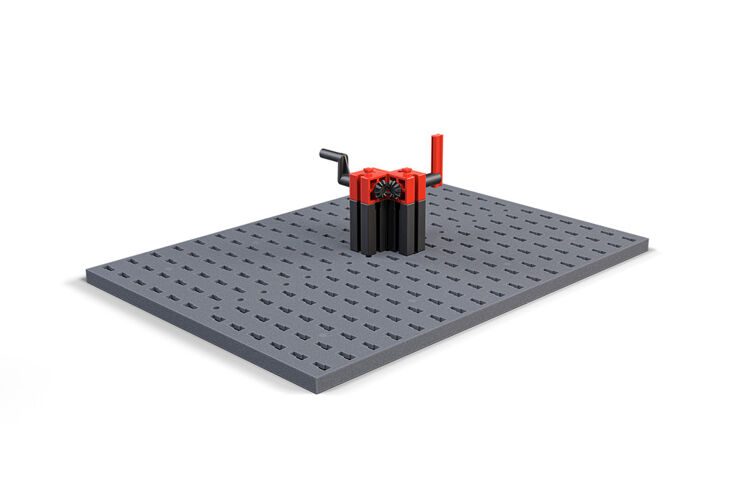
The unique thing about an impact driver is its hammer mechanism. The hammer mechanism creates small, rapid impacts while the drill tip turns. These impacts are transmitted to the tip of the driver and help penetrate the material.
Challenge:
The impacts in the impact driver are generated by two discs with angled teeth pushing against one another as they turn. A spring presses the drill tip with the rotating disc back, so that the teeth can interlock once again and create a new impact.
In impact drivers, the strokes (the distance travelled during the impact) are very short and fast.
Hammer drills have even more power than impact drivers. They also chisel during the drilling movement, and help remove material better.
Challenge:
The hammer mechanism in a hammer drill consists of a hammer that is accelerated by a coupler mechanism (like a crankshaft) and hits against the drill spindle. The impact causes the drill tip to move outward, while the hammer hits inward once again. Usually, the hammer is in a sealed tube so that the hammer never touches the crank at all, but is rather pushed away by air.
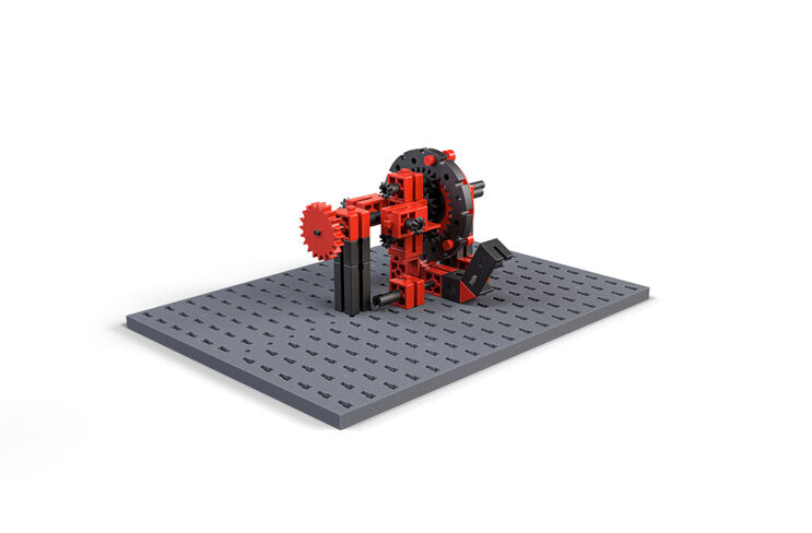
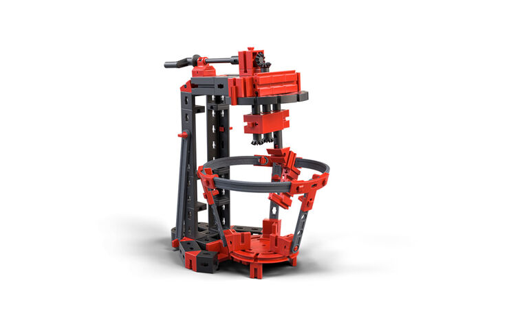
A planetary gear is a highly complex system of different types of gears. It is used in many different applications, such as agitators in food processors, or automatic transmissions in a car. However, the design in such applications is somewhat more complex.
Challenge:
You can use the pusher, which is the lever in the bottom part of your model, to arrest either the planetary wheel support or the ring gear, so that one of the two parts in each case can no longer turn.
The task of a planetary gear is simple. It makes it possible to change the gear ratio under load, e.g., without disconnecting the flow of force between the drive and output. Because the ring gear has internal teeth, the arrangement of the gears is very compact. In a planetary gear, no additional shaft with idler gear is required to move backwards.
In the simplest case, the planetary gear consists of a sun gear (1), planetary wheels (2), planetary wheel support (3) and ring gear (4). In this simple set of planetary gears, a sun gear in the middle is connected to a ring gear with internal teeth in a positive locking connection via multiple planetary wheels. The sun gear, planetary wheel supports or ring gear can each drive, be driven, or be arrested. You have the pusher so that you can test out the gears. Without an additional gear wheel, you can brake the planetary wheel support (3) to set the gear unit so that the output is carried out either via the planetary wheel support or via the ring gear. This process is used in motor vehicles to shift into reverse. In this case the drive (the shaft) must be connected to the sun gear and the axle drive must be connected to the ring gear.
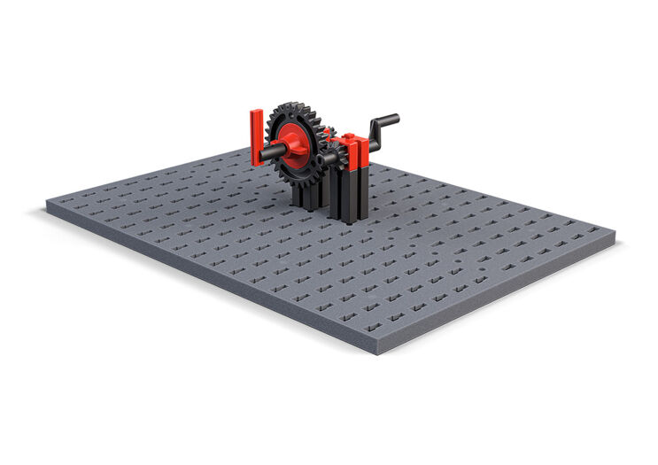
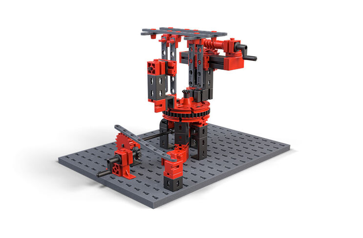
Worm gears transmit the rotational movement of an axle to the teeth of a toothed gear via a worm thread. As the worm thread turns, the toothed gear turns one tooth further. Since the output axle must run vertically to the input axle, a worm gear also changes the location of the movement.
Calculating transmission for a worm gear is very simple: The rotational speed of the input axle (the worm gear) is n times as great as the output axle, if n is the number of teeth on the toothed gear on the output axle. Therefore: If the worm gear drives a gear with 30 teeth, then you would have to turn the input axle 30 times for the output axle to turn once. Worm gears therefore are very high speed, and allow for compact gears with high gear ratios.
A worm gear is “self-locking”, and therefore only works in one direction: From the worm gear to the toothed gear. A worm gear is always used for gearing down.
The disadvantage of a worm drive is the significant loss of power of up to 30%, since the worm gear continuously rubs against the teeth of the toothed gear.
For solar cells to convert as much energy as possible, they need to be aligned properly to the sun. Solar trackers, which adjust the alignment of the cells, are used to do so. The challenge with such systems is that the angled solar cells want to pull the axis of the solar tracker downward.
This is comparable to holding a heavy object while your arms are stretched out in front of you.
Some solar trackers, therefore, use worm gears, because the secure locking effect of the worm gear prevents the solar tracker from pulling the holder down and “reversing” the drive.
Challenge:
You certainly needed to turn the crank several times to move the barrier 90°. Could you pull the barrier downward? As you can see, this is understood as a self-locking gearbox. You could use the small crank to easily lift the large barrier, meaning that you increased your drive force with the worm gear.
Worm gears have multiple advantages:
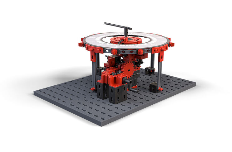
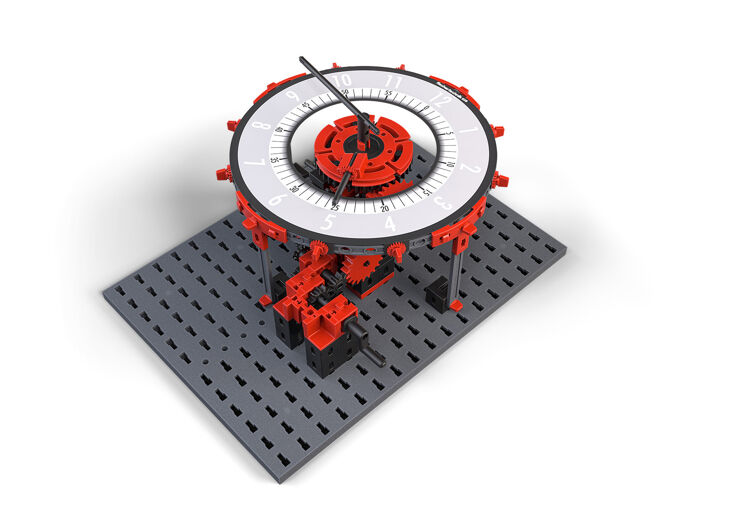
Whether digital or mechanical, we all use clocks every day. One of the most refined technical details of a mechanical clock is that multiple hands – at least the hour and minute hands – turn on the same axle at different speeds.
Challenge: