- Home
- Toys
- E-Learning
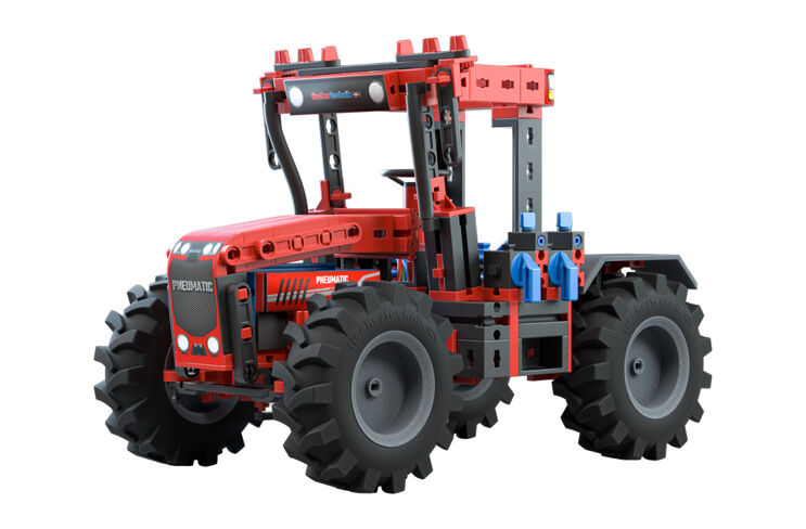
- Strong Pneumatics

Discover the power of compressed air through play!
To enable children to get to know and try out the topic of pneumatics, fischertechnik offers the pneumatics toy “Strong Pneumatics”, which with its realistic models and components enables quick and easy understanding and promotes technical imagination. 6 different models guarantee exciting adventures for young designers.
Compressed air is an indispensable part of everyday life. You probably encounter her in different forms every day. This can start with your morning breakfast egg, which may have been packed using pneumatic suction cups.
The word pneumatic comes from the Greek word “pneuma” and means “air”. Pneumatics is primarily about generating movements with air and performing mechanical work. You can drive almost anything with compressed air. It can be used as an alternative to muscle power or any other energy such as electricity, water, hydraulic oil or wind power.
Today, pneumatics are still everywhere in everyday life. Whether it’s inflating an air balloon, using a pneumatic hammer in road construction, diving with compressed air, painting, airbrush techniques, compressed air sirens, speed measurement with air jets on aircraft or large industrial systems - pneumatics are used everywhere!
What are the advantages of pneumatics?
The advantages of pneumatics are that …
We would like to explain these advantages and many other interesting information to you with the Strong Pneumatics module. We also want to show you how the pneumatic components work. To do this, we explain the individual components step by step and show how they work. The modular system also contains numerous model examples that illustrate how pneumatics can be used.

A little bit of history
Already in the third century BC, the Greek mathematician and inventor Ktesibios dealt with compressed air and the exciting possibilities it offers. He developed the first compressed-air-powered machines, such as a catapult that threw balls and spears with compressed air.
A very well-known compressed air system is that of Heron von Alexandria, who used the altar fire to generate compressed air and thus opened the large temple doors like a ghost’s hand. The heat from the altar fire heated the air in a pressure vessel that was half filled with water. When you heat air, it expands and the air pressure increases. The expanding air required more space and pressed the water from the pressure tank into a water tank, which lowered due to the increase in weight and thus opened the doors.
Pneumatics have been used as drive and control technology in industry since the beginning of the 20th century. In the construction and agricultural machinery industry, the topic of pneumatics is used to drive hammers and drills, for example. Suction and pressure pneumatics are also used in conveying technology, e.g. in grain mills for suctioning grain and conveying flour. We even find pneumatics in the music industry, for example in organ manufacturing. In a piano, a self-playing piano, the keys are pneumatically controlled. Pneumatic applications can be found in the automotive industry, the textile and food industry, electrical engineering, even in space, and in many other areas of everyday life.


