Entry-level-models

to become familiar with the components and programming

Grade
5-7
Time required
1 hour each / possibly with differentiation groups
Difficulty level
Model: easy, Programming: easy
Models
Circuit with LED and button, Circuit with LED and gesture sensor, Motor with rotational movement, Motor with vertical movement

MODEL DESCRIPTION / TASK

Eight simple basic tasks are designed to introduce pupils (SuS) to working with the STEM Coding Max experiment box. First, the structure of the RX controller, the controller configuration and the structure of the programming interface are clearly described. Simple switching operations are triggered using a sensor as an example. This processes information within a self-created program in the control system and, if necessary, switches an actuator or performs a function.

Key questions

  • What function can a switch fulfill? (communication)
  • What types of switches are there? (Communication)
  • Where is a function remotely switched or a switching operation triggered in everyday life? (Communication)
  • Which sensors can trigger actions? (Creativity)
  • What functions must a repetition loop and a time loop fulfill? (Communication)
  • Which actuators can be triggered by a switching operation? (Creativity)


Subject relevance

Information technology
Basics of programming
Physics
Sensors, actuators
Technology
Gear theory, basics of electr. circuit

Lesson plan


Introduction phase

Class discussion (without app)

  • Clarify in the class discussion which basic circuits can occur (connection of sensors, actuators, repeat loops, time loops, if-then functions, etc.).
  • Discuss what can be switched on or off (everyday examples).
  • Identify possible types of sensors: sensors for brightness, motion, switch-on, switch-off, switch-over, etc.
  • Name possible programming loops: switch-on delay, switch-off delay, time, repetition...
  • Name possible functions of actuators: turn, lift, illuminate, switch...

If necessary, provide assistance

  • Show sensors, actuators and components from the construction kit, use presentation media if necessary.
Planning phase

Class discussion

  • The basic structure of the app and its functions, e.g. help buttons, the function of the basic circuits, differentiation options, etc. are recorded and explained.
  • The sequence of the work steps in the app when working on a project is shown.

Class discussion

Preparation for the work phase:

  • The basic function of a switch (e.g. closed or open circuit), an LED (e.g. operating principle), a motor (e.g. operating principle) and their possible connection variants are discussed.
  • The triggering of the switching process and the desired change in the function of an actuator in a program are discussed.
  • The triggering of an actuator and its possible connection variants after the switching process are discussed.

Class discussion

  • The work to be done in the lesson is specified. The following eight basic tasks (switching operations; increasing in difficulty) are implemented as an introduction:

a) An LED switches on when the program starts.

b) A pushbutton switches an LED on and off again when the button is pressed.

c) A pushbutton switches an LED on and off with a time delay.

d) A pushbutton switches the flashing of an LED.

e) A hand movement is used to switch an LED on or off.

f) An LED is automatically switched on when it gets darker.

g) A motor performs a rotational movement.

h) A geared motor performs a lifting movement.

Partner or individual work

  • The students familiarize themselves with the app and load the corresponding task.
Construction phase

Partner or individual work

  • Pupils use the app to build the tasks. The app guides them through the program step by step.
  • The circuits are wired. The app guides them through the program step by step.
Programming phase

Partner or group work

  • The students write the program for the tasks. The app guides them through the program step by step; help is offered in the app.
  • The program is transferred to the RX controller after each programming step.
Experimentation and test phase

Partner or group work

  • The circuits are put into operation and tested.
  • Possible malfunctions in the functional sequence must be found and eliminated. Help is offered in the app.
  • Any optimizations in the hardware (e.g. loose cabling) and the programming of the output of the sensor command (e.g. time delay) are carried out.
Final phase

Presentation of

  • Procedure 1: Presentation of the circuits by a selected group of students.
  • Procedure 2: Presentation of the circuits by each group of students.

Discussion in plenary

  • Discussion of the further procedure in the following lessons.
  • Optional: Show a planned project for motivational purposes.


Information and notes


Methodological and instructive tips


Differentiation opportunities

Depending on the prior knowledge of the respective groups, they can work independently on the eight introductory tasks one after the other at their own pace.

Differentiation tasks can be set for particularly fast groups.

Examples:

  • Installation of a second LED of a different color, which then flashes alternately with the first LED.
  • Programming task in which one LED should light up when the motor is running clockwise and the other when it is running anticlockwise.

Motivational aspects

Building the basic circuits, which can be programmed using a “mini-computer”, has a motivating effect on many pupils. It is important to ensure that fears of the system or the possibly unfamiliar working methods are reduced or do not arise in the first place. Working independently with the support of an app is also becoming increasingly popular. The working rhythm and speed can be determined by the groups themselves. An additional motivating factor is that more complex construction tasks with an everyday relevance can be completed later on. 

Additionals materials

  • If necessary, use drawing media (paper, whiteboard, or projection screen) to introduce the topic.

Functions of the entry-level models and their technical solutions


Function of the sensors/actuators

Technical solution

a.) Switch an LED on and off

Displaying a signal with an LED

b.) Switch an LED on and off with a button

Evaluate a button signal and activate and LED

c.) Switch an LED on and off with a time delay using a button

Evaluate a button signal and acticate an LED after a time delay using a time loop

d.) Allow LED to flash after pressing the button

Evaluate a button signal and modulated control of an LED

e.) Manually switch an LED on and off

Evaluate the signal from a gesture sensor and activate an LED

f.) Automatically switch an LED on and off in the dark

Evaluate the signal from a brightness sensor and control of an LED

g.) Turn a motor left and right

Evaluate a button signal and motor control

h.) Raise and lower a motor slightly

Evaluate a button signal and motor control with independent return


Material list


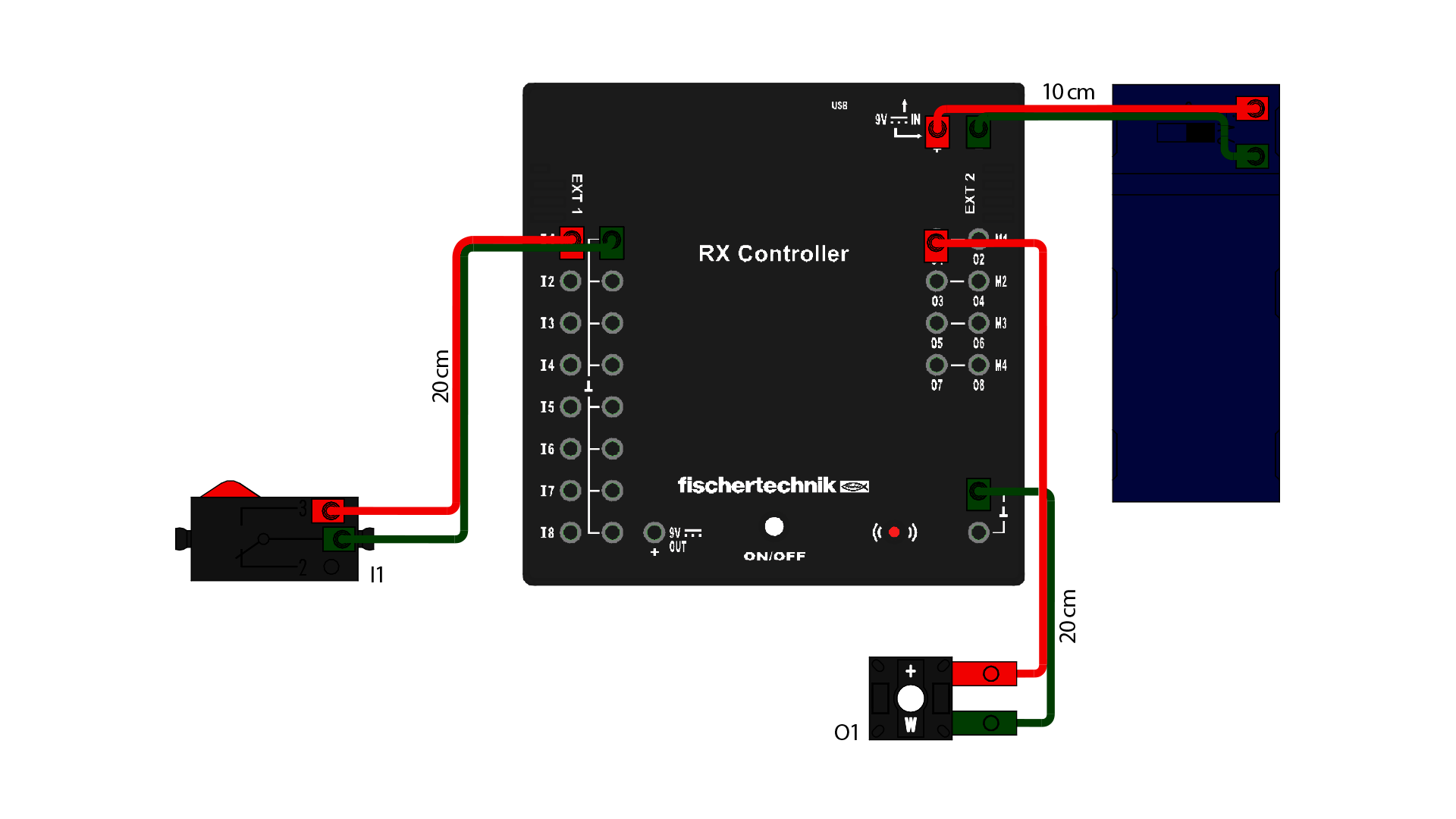
Entry-level model 1 (circuit with LED and button) – Basic tasks a) to d)

Sensors

Function

1 button

Trigger the switching signal

Actuators

Function

1 LED, white

Lighting


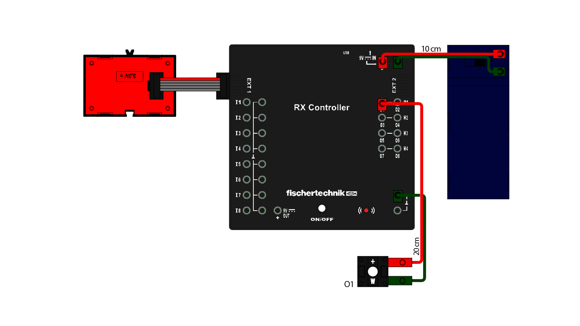
Entry-level model 2 (circuit with LED and gesture sensor) – Basic tasks e) to f)

Sensors

Function

1 RGB gesture sensor

Trigger the switching signal

Actuators

Function

1 LED, white

Lighting


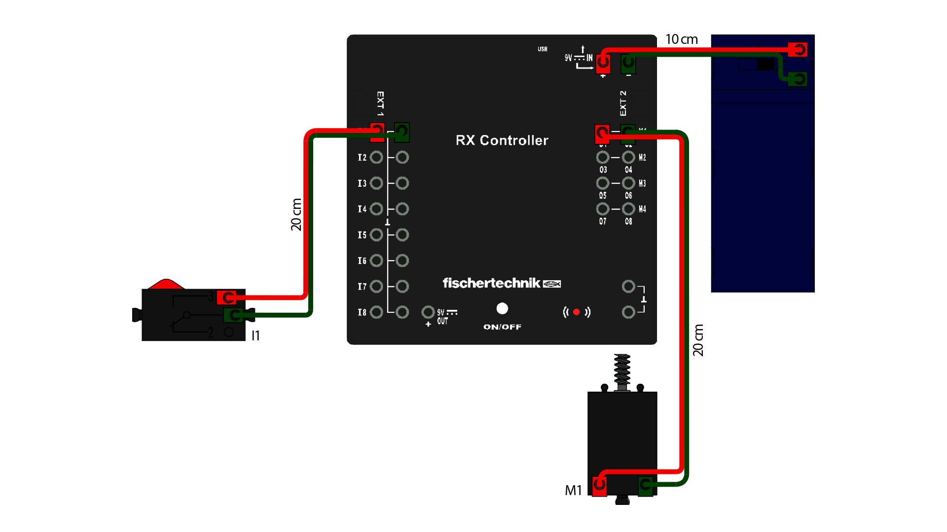
Entry-level model 3 (motor with rotational movement) – Basic task g)

Sensors

Function

1 button

Trigger the switching signal

Actuators

Function

1 motor

Rotary movement


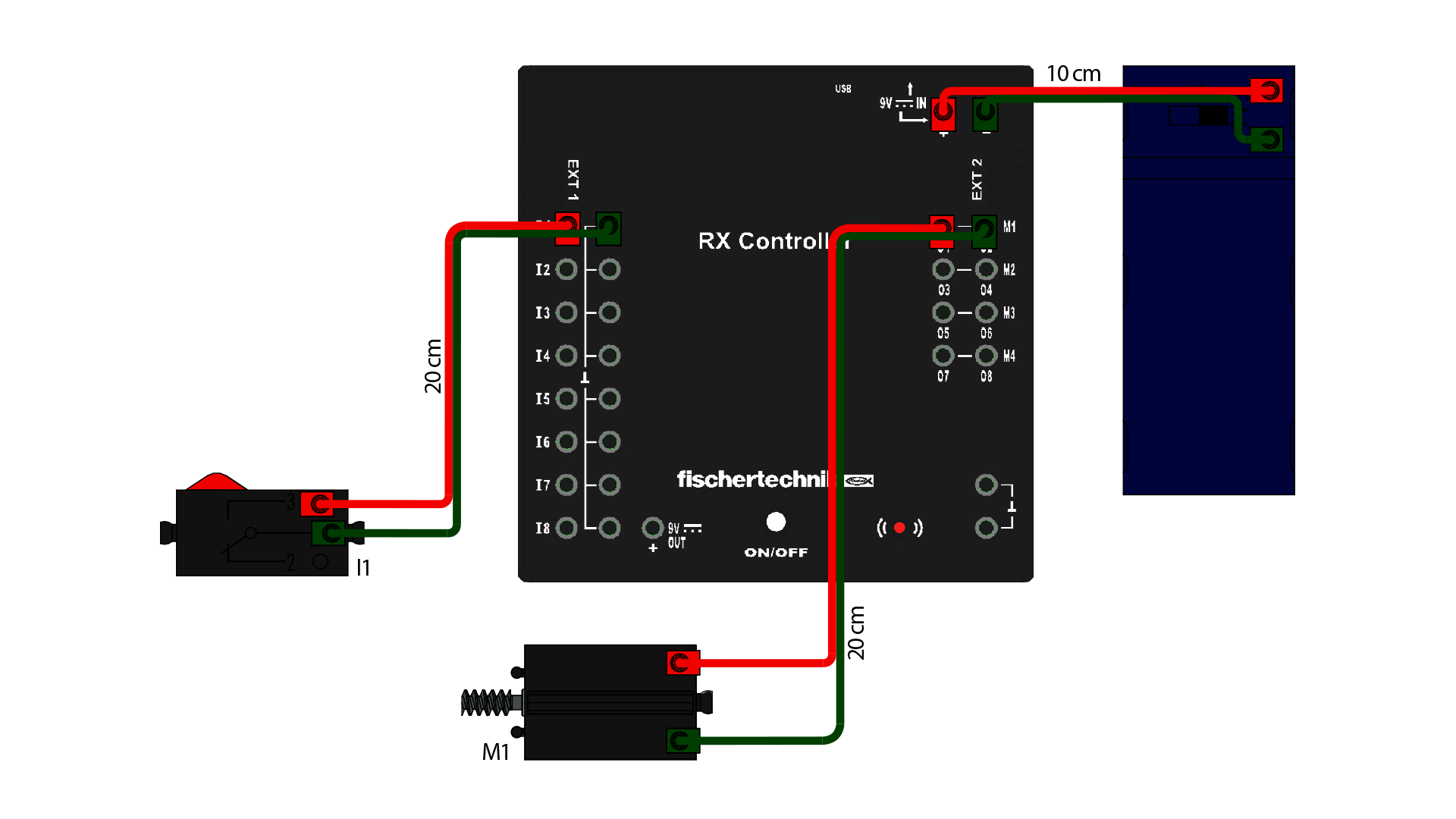
Entry-level model 4 (motor with vertical movement) – Basic task h)

Sensors

Function

1 button

Trigger the switching signal

Actuators

Function

1 motor

Linear movement


Differentiation

Sensors

Function

1 button

Trigger the switching signal

Actuators

Function

1 motor
1 LED red
1 LED green

Linear movement
Lighting
Lighting


cd-green-58bb58464c-tb9pl