Make the basics of robotics understandable and sustainable!
The fischertechnik Robotics TXT 4.0 Base Set is the perfect start to programming like the pros! In addition to the camera with image processing, the comprehensive construction set contains an ultrasonic sensor, two encoder motors, a track sensor, a phototransistor as well as two buttons and two LEDs. The models can be programmed and controlled using the ROBO Pro Coding graphical programming software and the ROBOTICS TXT 4.0 controller. Beginners can use ready-made example programs, while advanced and professional users can get started directly in a Blockly programming environment or in Python. Included are 12 exciting models, ranging from pedestrian traffic lights to a barrier, a barcode scanner and mobile driving robots with encoder motors, camera, track and distance sensors. In addition to introductory and basic information, the comprehensive teaching material includes 20 experiments with solutions for the 12 models.
Computers have become an integral part of our modern world. They surround us not only in the form of PCs, laptops or tablets: we carry them in our pockets as smartphones, they are in our cars, in dishwashers and washing machines, in heating controls, in e-bikes and in coffee machines.
Year after year, they are becoming more powerful and at the same time smaller and more compact. As a result, their fields of application are also increasing, as they can now be tailored to the respective application and integrated into it as "embedded systems". They use sensors to detect and "measure" their environment and control motors, LEDs or other actuators. Using modern wireless communication technologies such as WLAN or Bluetooth, they can be networked with each other and exchange data with each other or with a control center.
But how do such embedded systems and their respective "heart", the microprocessor, work? What is a microcontroller and how is it used to record and evaluate sensor data? How do you control mobile systems, e.g. robots or vehicles? How can the systems communicate with each other and exchange data?
This learning unit focuses on understanding microcontrollers and their use. The central basics are explained and their practical implementation is deepened in the exercises (tasks). Various important areas of application for microcontrollers are presented: Measurement, communication, coding and encryption, control and regulation, robotics and autonomous driving.
Definition
A microcontroller is a control system consisting of a microprocessor and a number of inputs and outputs. Sensors or memories are connected to the inputs, while actuators such as motors, LEDs or displays are connected to the outputs. Microcontrollers have a volatile working memory (RAM), which is deleted when switched off, and usually also have an EEPROM in which programs and data can be permanently stored. In contrast to laptops and PCs, there is neither a keyboard as an input unit nor a screen as an output unit; these must be controlled separately.
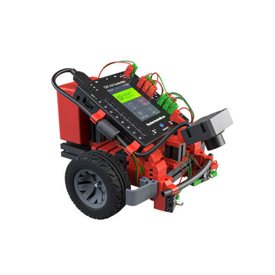
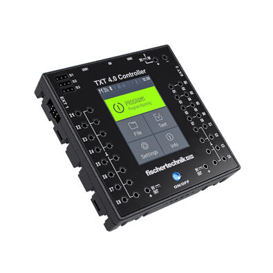
Well-known and widespread representatives of such microcontrollers are, for example, the Arduino, the BBC micro:bit, the Calliope Mini and the TXT controller from fischertechnik.
The heart of the microcontroller is a microprocessor. In itself, a microprocessor is an integrated circuit (IC) that loads instructions and data from a (temporary) memory - called random access memory (RAM) - into the IC's registers, processes them in a computing unit and stores the result back in RAM. A microprocessor essentially consists of transistors - electronic "switches" that know exactly two states: "on" and "off". These transistors can be used to construct logical circuits such as "and", "or" and "not" links. The results are stored in a "flip-flop", a stable toggle switch (for more details, see the "Electronics" education box).
A quartz crystal sets the clock for the microprocessor, i.e. the speed at which the microprocessor processes the instructions and internal calculation steps. The instructions are specified in a machine code (which varies depending on the type of microprocessor) and consist of a command (e.g. "add two values") and, depending on the instruction, several parameters (e.g. the two values to be added or the registers in which the values are stored).
The performance of the microprocessor is determined by the clock speed, the data width in bits (which indicates how large the addresses and values may be that the microprocessor instructions can process in one step) and the machine code itself: The more complex the instructions that the IC can execute, the faster, as a rule, the data processing. To speed up access to the RAM, many microprocessors today contain their own cache memory in which they temporarily store instructions and data during processing.
The microprocessors used today in laptops and PCs can process 64-bit long data (values, RAM addresses), contain several billion transistors and are clocked at several GHz (billions of oscillations per second). They can share the work ("multi-core") and have many megabytes of cache memory. In microcontrollers today, microprocessors with a word width of 32 bits and a clock frequency of less than one GHz are usually used - this is by far sufficient for the tasks of a microcontroller.
History
Since ancient times, people have been experimenting with automata - constructions which, driven by air or water power, perform work independently, execute predefined motion sequences on command or even produce music. In the 15th century AD, Leonardo da Vinci (1452-1519) constructed numerous machines that impressed the people and nobility in theaters and royal courts. Wolfgang von Kempelen (1734-1804) built a functional speech synthesizer in 1791. The punch card control system for mechanical looms developed by Joseph-Marie Jacquard (1752-1834) in 1805 is considered the first "programmable automaton".
However, the breakthrough for the development of flexible control systems only came with the development of the computer. The invention of the integrated circuit (IC) in 1958/1959 by Jack Kilby (1923-2005) and Robert Noyce (1927-1990) and the development of the microprocessor in 1971, invented and patented by engineers at Texas Instruments, made very flexible, lightweight, fast and wear-free, but above all programmable controls possible. The first microprocessor, the TMS1000, contained 8,000 transistors. Since then, the number of transistors in a microprocessor has doubled approximately every 18 months. This development is also known as "Moore's Law" after Gordon Moore (*1929), who derived this correlation in 1965 from the further development of ICs in the preceding years. Today's microprocessors consist of several billion transistors - and are barely larger than the TMS1000.
How is a microcontroller programmed?
The microcontroller is usually not programmed on the microcontroller itself, but in a special programming or development environment (integrated development environment, IDE) on a PC, laptop, tablet or even a smartphone. Programs created in this way are then transferred to the microcontroller's memory via a communication interface, e.g. USB, WLAN or Bluetooth, and executed there.
This is exactly how the TXT 4.0 is programmed: The programs are developed in ROBO Pro Coding on a PC, laptop or tablet in the Blockly or Python programming language and then transferred to the TXT 4.0, on which they are executed.
What is a "finite automaton"?
A "finite automaton" is a system whose behavior can be described as a finite set of states. The transition from one state to another is triggered by conditions (such as events, e.g. changes in sensor values), each of which is followed by an action. Finite automata are therefore also called "state machines" and are described by state transition diagrams.
Finite automata play an important role in the description of microcontrollers: almost every embedded system (such as an elevator controller or a robot) can be understood as a system consisting of a finite number of states. The representation as a state transition diagram usually simplifies the understanding of the system considerably and facilitates (above all error-free) programming. This is because in each state, only the events that lead to a state change need to be taken into account, such as the request for a "green" signal at a pedestrian traffic light (see the example in the figure).
What is analog and digital data?
Microcontrollers can only process "on" and "off" states, i.e. binary values that can assume two different states. The evaluation of sensors that also only know two states, such as buttons, reed contacts (magnetic switches) or phototransistors, is therefore very simple, and the state of the sensor can be stored as digital data in one bit.
But in reality, of course, there are not only binary states. For example, brightness, temperature or distances can take on many different values. We can also measure such analog data with sensors, such as a photo resistor, a thermistor (thermistor) or an ultrasonic distance sensor. However, in order for our microcontroller to process these analog values, it must convert them into numbers, i.e. digital data. However, these are more complex values than the binary values provided by the digital sensors: Based on the binary states, the microprocessor can represent all numerical values using the dual system (and, by means of suitable coding, also other characters, such as letters, but more on this later).
The conversion of the analog sensor value into a number (i.e. a more complex digital datum) is performed in a microcontroller by an analog-to-digital (A/D) converter: the applied sensor value, usually an electrical resistance or a voltage, is electronically "scanned" for this purpose. If the resistance or voltage is high, the A/D converter delivers a large numerical value; if the analog value applied is low, the numerical value delivered to the microcontroller is small. How precisely the analog value present at the input can be determined depends on the resolution of the A/D converter. This is usually specified in the bit length of the result value.
The eight inputs of the TXT 4.0 controller can be used both as digital (binary) and analog inputs. The A/D converters at the inputs sample analog values such as the electrical resistance of the thermistor, which changes depending on the temperature, with an accuracy of 12 bits, i.e. they convert the resistance into a number between 0 and 4096. Thanks to different reference voltages, the TXT 4.0 can not only precisely determine resistances in the measuring range of 5 kOhm, but also significantly higher resistance values.
What is concurrency?
How do you determine the temperature with a thermistor?
A thermistor (also known as a thermistor or NTC resistor) is a resistor whose resistance value changes depending on the temperature. Thermistors have a negative temperature coefficient (NTC), i.e. the resistance value decreases as the temperature rises. The following diagram shows the resistance characteristic of the fischertechnik thermistor.
The fischertechnik thermistor has a resistance value of 1.5 kOhm at 25°C. As can be seen from the graph, the characteristic curve of the thermistor is not linear. However, you can approximate the temperature value reasonably accurately using a linear curve. To do this, you must determine a second measured value and calculate the equation of the linear function from it.
For a more precise calculation of the temperature value T (in Kelvin) from the resistance value R of an NTC resistor, the following Steinhart-Hart equation is usually used:
1/T=a+b(lnR)+c(lnR)³
The temperature in °C is obtained from T by subtracting 273.15.
With two additional measured values (in addition to the resistance value of 1.5 kOhm at 25°C), we can set up a system of equations with the three unknowns a, b and c. We do not have to solve this system of equations ourselves. We do not have to solve this system of equations ourselves: On the Stanford Research Systems website there is a "Thermistor Calculator" that calculates the parameters of the Steinhart-Hart equation we are looking for from the three measured values.
How does the ultrasonic sensor work?
What is a code?
How do computers communicate?
Wie funktionieren Barcodes?
Ein Barcode ist ein „Balkencode“ oder Strichcode, der aus schwarzen und weißen senkrechten Balken verschiedener Breite besteht. Barcodes zählen zu den eindimensionalen Codes, da die Information allein in der Breite der Balken enthalten ist (bspw. schmaler Balken = „0“, breiter Balken = „1“). Die Farbe der Balken (s/w) dient allein deren Unterscheidung. Barcodes sind „optische Codes“, d. h. sie können von einem Sensor, der „hell“ und „dunkel“ unterscheiden kann, oder von einer Kamera mit Bildauswertung gelesen werden. Barcodes werden überwiegend zur Kennzeichnung von Objekten verwendet; man findet sie z. B. auf Büchern und Zeitschriften (ISBN/ISSN), auf Waren-Etiketten oder Aufklebern für die Paketpost. Es gibt sehr viele unterschiedliche Barcodes, die sich durch ihre Informationsdichte und durch die verwendeten Prüfziffern unterscheiden. Barcodes haben den Vorteil, dass sie sehr robust sind und leicht eingelesen werden können; auch sind die Lesegeräte sehr günstig.
Ein typischer Barcode ist der Code 39. Er wurde bereits 1973 bei der Fa. Intermec entwickelt und inzwischen von diversen Normungs-Organisationen (darunter ANSI und ISO) in Spezifikationen bzw. Normen festgelegt (u. a. der ISO/IEC 16388). Ein Code-39-Zeichen besteht aus neun Balken – fünf schwarzen und vier weißen (den Zwischenräumen) – in zwei verschiedenen Breiten. Dabei steht ein breiter Balken für eine „1“ und ein schmaler für eine „0“; ein Code-39-Zeichen entspricht also einer neunstelligen Binärzahl.
Vor und hinter jedem Zeichen folgt ein (schmaler) weißer Zwischenraum, damit man die einzelnen Zeichen unterscheiden kann. Code-39-Barcodes sind immer gleich breit, denn die Anzahl der breiten Balken je Zeichen ist auf genau drei festgelegt: zwei schwarze und ein weißer. Ein Code-39-Zeichen besteht also immer aus sechs schmalen und drei breiten Balken, oder sechs „0“-en und drei „1“-en. Der Code-39-Standard definiert insgesamt 44 Zeichen: die 26 Buchstaben des Alphabets, die zehn Ziffern „0“ bis „9“ und die acht Sonderzeichen „*“ (Start-/Stoppzeichen), Leerzeichen, „-“, „+“, „.“, „/“, „%“ und „$“.
Eine Weiterentwicklung der Barcodes sind QR-Codes, die aus Punkten auf einer quadratischen Fläche bestehen. Sie zählen zu den zweidimensionalen Codes und erfordern eine Kamera zum Einlesen und Dekodieren.
What is Morse code?
How does the RGB color code work?
The RGB code is a three-byte coding of the color components R (red), G (green) and B (blue, each from 0-255) in a hue. The color tone (hue) can be determined from an RGB value as follows:
The result is the angle at which this color lies in the color wheel (see illustration).
What is redundancy?
How does encryption work?
What is a controller?
Download the ROBO Pro Coding App
Before you can get started, you need to download the ROBO Pro Coding App. Simply select the appropriate operating system and click on the link:
Download Voice Control
Tell the robot where to go! Simply download our Voice Control app and give the robot individual commands: